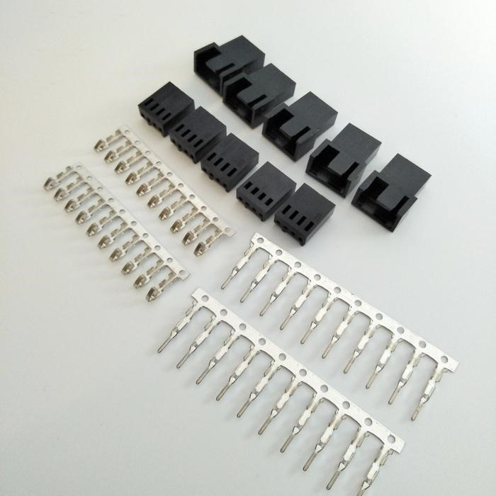
In the cooling system of electronic equipment, the connector is the connection hub between the fan and the circuit, and its model selection is directly related to the stability and energy efficiency of the system. The seemingly simple combination of numbers and letters actually contains the precise matching logic of electrical characteristics, mechanical structure, and application scenarios. This article will break through the surface model cognition, deeply interpret the technical code behind the connector model, and provide engineers and electronics enthusiasts with a complete knowledge system from principle to practice.
The model code of the cooling fan connector is a condensed expression of electrical parameters and physical characteristics. Although there are differences between different brands, the core elements are highly unified. Taking the industrial-grade connector "TE Connectivity 1-179268-2" as an example, its coding logic can be broken down into the following:
This coding method is based on strict industrial standards: the spacing error must be controlled within ±0.05 mm, and the plug-in life must be no less than 500 times (IEC 60352-2 standard). Test data from an automotive electronics laboratory shows that when the terminal spacing deviation exceeds 0.1 mm, the contact resistance will surge by 30%, resulting in an additional 2.5 W of power consumption when the fan is running.
The standardized evolution of pin functions deserves special attention:
The differences in connector models are not only reflected in parameters but also hide the choices of material science and manufacturing processes. High-end models of mainstream brands such as the Molex 43045 series adopt:
Comparative tests show that the contact resistance change rate of the connector using the above process is <5% after 1000 hours of continuous vibration test (10-2000 Hz), while the ordinary brass connector is 15%-20%. This is also the core reason why industrial equipment strictly specifies the connector model.
In extreme environments, the choice of connector model directly determines the reliability of the system:
Establishing a scientific selection process requires considering multi-dimensional parameters:
The transformation case of a data center is quite valuable for reference: after replacing the traditional 3-pin connector with a 4-pin PWM model, the overall power consumption of the computer room was reduced by 18% through intelligent speed regulation, and the fan life was extended to 60,000 hours (an increase of 50%). This is due to the refined control capability brought by the connector, which enables the fan speed to be dynamically adjusted according to the CPU load.
The common model verification methods used by engineers include:
For purchasing personnel, it is recommended to establish a "connector model-device model" correspondence table, for example
|
Equipment Type |
Recommended Connector Model |
Key Parameters |
|
Home PC |
Molex 39-01-2040 |
4-pin PWM, 2.54mm |
|
Industrial Control Cabinet |
AMP 174925-3 |
3-pin, 3.96mm spacing |
|
Medical Equipment |
JST XH-2 |
2-pin, UL 94 V-0 certified |
Understanding the deep meaning of the cooling fan connector model is essentially mastering the connection language of the electronic system. From millimeter-level spacing control to micro-ohm-level resistance optimization, each model number is the crystallization of engineering wisdom. In today's pursuit of high-performance equipment, ignoring the choice of connector models is like equipping a precision watch with inferior gears—seemingly minor negligence may cause systemic failures.